History
Since 1986, ADAM Technology engaged in the design, manufacture, and marketing of a range of analytical stereoplotters. These are essentially high-precision electronic, opto-mechanical measuring systems, mainly for the aerial survey market.
ADAM Technology has now increased its product range into the area of automatic measurement. The know-how and expertise acquired in photogrammetry and the manufacturing of stereoplotters formed the cornerstone of this new development. ADAM Technology undertook a major research project to develop the technology able to perform automatic 3D measurements for the manufacturing, mining and associated industries.
3-dimensional
All the measurements are 3-dimensional - all of the resulting measurements are in XYZ coordinates. We achieve this by using two or more cameras to obtain stereo images of the objects to be measured.
Dynamic
Using sophisticated CCD camera systems, we can trigger two or more cameras automatically and simultaneously. This allows us to analyse objects that travel rapidly or change shape.
3DM's Features and Characteristics
The main objective of the 3DM project was to develop the technology capable of measuring 3-dimensional data on moving objects and have the results available within seconds rather than hours. Such data can be typically used as feed-back within a manufacturing process.
3-dimensional
The system measures 3D data; that is, the X, Y, and Z coordinates of common object points in ground co-ordinates.
High speed
Over 4000 points per minute can be measured automatically on a modern, low-cost PC. (Based on a 366MHz Intel Celeron-equipped PC finding 636 3D points in a pair of images (each 640x480 pixels) in 8 seconds.)
Repetitive
The system is designed for repetitive and automatic measurements, which once started, doesn't require any operator intervention, potentially operating 24 hours per day.
Contact free
The system uses monochrome CCD cameras, which are essentially video cameras, to image the surface of the objects from at least two positions.
This means it is a contact-free measuring method. The advantage over contact measurement is that it allows objects to be measured that are either moving, changing shape, too dangerous to handle (e.g. very hot), too big, or too flimsy to be measured any other way.
Accuracy of a 3DM system
The system can be tailored to achieve the accuracy required. The higher the accuracy required, the slower the measuring process will be. Typically surface points are measured with an accuracy of around 1/1000 of the size of the object measured.
Size of objects that can be measured
Almost any size object can be measured, as long as it can be imaged using a CCD camera. Typically a mine site would be the upper size limit, the lower limit would be objects in the millimetre range.
Keeping permanent record
The 3DM system can store all the images acquired during the measuring process, and therefore provide a permanent record of the measured object at that exact time.
How Does It Work?
Photogrammetry
Photogrammetry is defined as the art, science, and technology of obtaining reliable information about physical objects through processes of recording, measuring, and interpreting photographic images.
The 3DM technology is based on photogrammetric technology. With the 3DM technology we obtain accurate 3D spatial measurements of objects by analysing images taken with CCD (video) cameras. A minimum of two cameras are required for stereo measurements.
The camera positions are evaluated for each project. We find the optimal compromise between accuracy of measurements, reliability, and object coverage.
Calibration
To achieve the desired accuracy, the lenses and cameras need to be calibrated. The calibration is based on a surveyed target range and can be easily done on-site or in the ADAM laboratory.
Exterior Orientation
The exterior orientation of a camera is defined as the position of the projection centre of the camera in space (X,Y,Z) and 3 rotation angles describing the orientation (direction of the camera axis). Sophisticated software helps the operator to determine the exterior orientation of the cameras from a minimal number of surveyed control points.
3D Measuring
The system can be started once the parameters for the measuring cycle have been determined. It will then automatically and repetitively measure objects, store all the data and images in a database, and can even send the measurements over a network to another computer.
The system takes at least two images of an object and analyses the images to find the positions of the common points. With the knowledge of the camera position and orientation, it can compute the 3D coordinates of object points.
Using a digital camera system allows us to trigger up to 6 cameras simultaneously, thereby creating instantaneous records of the object. This enables the system to measure moving objects or objects that can change shape rapidly.
3D Measuring Techniques
There are essentially three techniques available for measuring 3D points on objects: using targets, edges, or surface points. ADAM Technology has implemented all three options, ready to be combined and built into any customised system.
 |
| Figure 1. Part of a calibration frame |
Targets are usually circular white dots on a black background. These targets are placed manually on the objects in the location to be measured. Because the targets are circular, the system is able to find the target centres very accurately using a centroid algorithm. Using this technique allows targets to be measured with much higher accuracy than edges or surface points.
The drawback with targets, however, is the preparation required. Surface points and edges usually do not require any preparation. ADAM Technology generally uses targets only on calibration frames and target fields required for the calibration of lenses and cameras and the computation of exterior orientations.
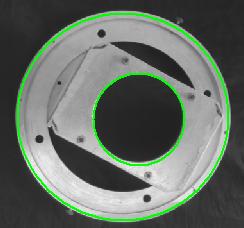 |
| Figure 2. Circles detected on a machined component |
The technique of measuring edges is most suited to machined components with sharp edges. The edges of the components must be visible in the images taken. These edges are extracted automatically and lines or ellipses fitted to the image edges. 3D information such as the length, width, and height of objects, and the diameters and centres of holes, is then computed. This method usually needs no preparation of the object and is most suited for repetitive measurements of mechanical components.
Surface points are computed using Image Correlation techniques, which automatically identify matching points in two or more images. Once the common points are identified, 3D coordinates for these points are computed. Surfaces on objects are then described by a "cloud of 3D points" -- in surveying terms, a DTM (Digital Terrain Model). These points are usually displayed by forming a triangular mesh over the surface. The DTM can be exported in a variety of formats, including AutoCAD DXF format.
Example images
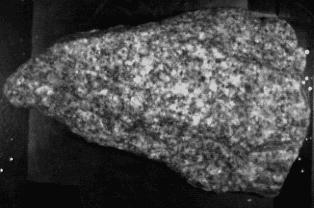 |
| Figure 3. Original image (left camera) of a rock |
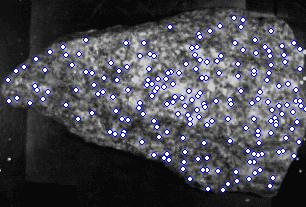 |
| Figure 4. Computed 3D surface points displayed as white dots |
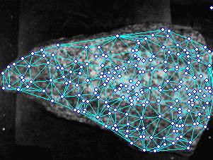 |
| Figure 5. DTM triangles formed from computed 3D surface points |
 |
| Figure 6. Rotated 3D view of the DTM using OpenGL |
Texture projection
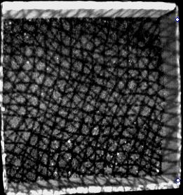 |
| Figure 7. Pattern projected onto a featureless surface |
Image correlation relies on surface texture to work. It won't work well on smooth surfaces without any texture. However, texture can be projected onto the object using a modified slide projector. For smaller objects we prefer to project a pattern in any case to increase the number of correlated points. The size limit for pattern projection is approximately 5 metres x 5 metres. For larger objects, like mine sites, the natural surface texture and relief is adequate.
Figure 7 shows an irregular grid pattern projected onto a tray of black volcanic sand.
Stereo Viewing
The 3DM technology has been targeted to work fully automatically, without any operator input. However, there are a number of applications where manual measurements are required. Also, during system setup it is most helpful to be able to view objects and the DTM points in 3D. For this purpose we have implemented support for the Stereographics Crystal Eyes LCD shutter glasses for stereo viewing.
When in stereo mode, the software alternately displays the left and right images in a window while an infra-red transmitter placed on top of the monitor synchronises the LCD shutter glasses with the monitor's display. The monitor is configured to refresh the display at at least 100Hz to prevent flicker. The operator can view the object in stereo, overlay the DTM points and triangles in stereo, and even drive a floating mark around in 3D using the mouse, adding and deleting points at will. Users who have used softcopy photogrammetric systems in the past will be familiar with the technique.
We also have available the Stereographics Z Screen and polarising glasses. This system is especially useful where 2 or more people are viewing the one screen. This is the type of system most useful in a teaching environment.
Lens/Camera Coverage
The table below shows the maximum object size that can be imaged from a distance of one metre with commonly used cameras for a range of lenses.
| Focal length of lens | Camera type: | Pulnix 6CN (analog) | Pulnix TM-9700 (digital) | ||
|---|---|---|---|---|---|
| CCD sensor format: (mm) | X (horiz) | Y (vert) | X (horiz) | Y (vert) | |
| 6.4 | 4.8 | 8.9 | 6.6 | ||
| 4mm | 1/2 Field angle (degrees) | 38.7 | 31.1 | 48.0 | 39.5 |
| Maximum object size (m) | 1.6 | 1.2 | 2.2 | 1.7 | |
| 12mm | 1/2 Field angle (degrees) | 14.9 | 11.4 | 20.3 | 15.4 |
| Maximum object size (m) | 0.5 | 0.4 | 0.7 | 0.6 | |
| 25mm | 1/2 Field angle (degrees) | 7.3 | 5.5 | 10.1 | 7.5 |
| Maximum object size (m) | 0.3 | 0.2 | 0.4 | 0.3 | |